Module 11
Case Files
What you’ll be able to do
Transfer the method to unfamiliar failures without hindsight bias.
Course plan & prerequisites · Scope and sources · Revision 2026-09-10
On this page
Study an annotated diagram
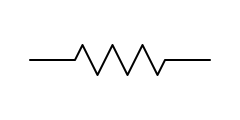
R
Limits current and drops voltage. On the bench: measure resistance in-circuit only with power off, and expect parallel paths to read low — lift one leg to be sure. Open resistors usually show a burn mark or read OL.The modules taught you tools and process; the Fault Drills made you choose measurements. This module is the third leg: six complete repairs, told the way they actually unfold at a bench — including the wrong turns. Read them for the shape of the thinking: ticket → ritual → ranked hypotheses → the measurement that splits them → the pivot when a reading surprises you → root cause → paperwork. Every board here is generic and invented; the reasoning is the real cargo.
Case 001 — The rail that wasn't dead, and the regulator that wasn't guilty
The ticket. Generic 28 V engine-interface card, functional test: "All +5 V domain outputs inactive. +5 V test point measured 0.02 V, limits 4.75–5.25." Hard failure, first visit for this serial number.
First five minutes. Microscope pass: clean board, no burns, no bulged cans, no cracked ceramics, connectors unbent. Conformal coat intact. No rework history. The visual buys nothing, which is itself data — whatever died, died quietly.
Pause: write your next measurement, then reveal the investigation
Hypotheses, ranked by prior. A dead rail with a quiet visual: (1) the regulator was never fed — something upstream open; (2) regulator failed; (3) hard short on the 5 V net holding it down; (4) enable/sequencing never asserted. I rank "never fed" first because the module drilled it: don't condemn a regulator that's never been fed — and open feeds (fuse, bead, connector pin) are boring, common, and cheap to check.
The splitting measurement. Before probing, I write the predictions: if the net is healthy, rail-to-ground ohms should read in the same few-kΩ neighborhood as the golden board; if hypothesis 3 is right, near zero. Power off, ohms from the 5 V net to ground: 1.8 kΩ, and the golden board reads 1.9 kΩ. That kills hypothesis 3 in one reading — no short, and no need for any of the short-localization ladder. Power on, current-limited supply, and the board draws far less than expected — the too-low signature, something not starting. DMM on the regulator: output 0.02 V… and input 0.03 V. The regulator never got breakfast. Hypotheses 2 and 4 just became irrelevant; the fault is upstream of the regulator's input pin, and the remaining suspects are exactly the parts in that feed path.
The pivot. The schematic shows 28 V arriving through a fuse, then a ferrite bead (FB2) into the regulator's input node. Fuse beeps fine — surprise number one, because I'd already mentally written "open fuse" on the traveler. The bead is next in line: continuity across FB2 reads OL. Beads are DC continuity; an open bead silently starves everything behind it. There it is.
Root cause. Under the microscope at an angle, FB2's far termination shows a hairline ring crack — a cracked joint, not a failed bead body. This board's bead sits close to a mounting standoff: torque flex during installation is the plausible mechanism, and the repair note says so, because the next board in the fleet with this symptom shouldn't take an hour.
The traveler. Symptom: +5 V rail absent. Cause: open solder joint, FB2 termination (visual ring crack, OL across part). Action: joint reworked per 7711/7721, bead re-verified continuity, coat restored. Verification: rail 5.03 V, full ATP pass. Root-cause note: mechanical stress proximity to standoff; recommend fleet watch.
The inefficient version replaces the regulator first — it was "obviously dead" — then discovers the new regulator is also mysteriously dead, powers the board a third time hoping for different physics, and finds the bead an hour later, having also spent a heat cycle on a fine-pitch rework the board never needed. Every unnecessary rework is a new chance to crack a neighboring ceramic. The one habit that prevents all of it costs ten seconds: measure the input before condemning the box that makes the output.
Case 002 — The board was fine
The ticket. ICT reject, generic avionics I/O card: "C88 measured 78 nF, nominal 100 nF, limits 90–110." Second board this shift with the same line item.
First five minutes. C88 under the scope: joint fillets textbook, part intact, no flex damage near it, no rework anywhere on the board. Then the history check in the datalog — and this is the move that matters, because the ticket names a component but the fleet names the pattern: the same test has failed five of nine boards this week, different serial numbers, and three of them retested PASS after re-seat. The measured values scatter, too — 78, 84, 71 nF on boards whose caps come from different date codes. A component lottery doesn't behave that way; a degrading contact does.
Pause: write your next measurement, then reveal the investigation
Hypotheses, ranked. (1) Fixture: worn or dirty pogo pin on that net, debris on the pad; (2) a genuinely marginal cap lot; (3) real assembly defect recurring. Fixture goes first — when the same test wobbles across many boards, suspect the one thing they share.
The splitting measurement. Bench LCR check of C88 in place, guarding irrelevant at this impedance: 99.1 nF. The golden board's C88: 99.4 nF. The board's part is healthy; the tester's claim doesn't reproduce at the bench with good contact. That's the split: board physics says fine, machine says fail — the disagreement itself localizes the fault to the interface between them.
The pivot. I asked the test tech to pull the fixture plate. The pogo pin for that net has a flattened, gunked crown, and its witness mark on the board's test pad is a faint smear where its neighbors leave crisp dimples. Surprise resolved: intermittent contact resistance in series with a capacitance measurement reads as low-C, exactly the drift pattern in the datalog.
Root cause. Worn, contaminated test pin. The board was fine — the test fixture was the fault. Pin replaced, fixture self-test run, all five "failed" boards retested clean and the week's Pareto entry closed with a fixture-maintenance note instead of five bogus cap replacements.
The traveler. Cause: no board defect — test anomaly, fixture pin J-block 14 replaced by test engineering. Verification: full ATP pass ×2, plus the re-run of the four sibling boards logged against the same finding. The NTF is documented as a fixture finding, not shrugged off — an NTF with an explanation is a closed case; an NTF without one is a time bomb sitting in the fleet's history, waiting to teach the next tech the wrong lesson.
The inefficient version replaces C88 on five boards, "fixes" three of them by accident of contact, and teaches the shop a superstition. Nobody looks at the datalog. The pin keeps wearing. Repair techs are the feedback loop of a test floor; this case is that sentence with a serial number on it.
Case 003 — The transceiver was the victim
The ticket. Generic 28 V data-concentrator card, functional test: "Serial bus B: no response to interrogation. Transceiver output differential 0.0 V." Squawk history from the aircraft, quoted in the work order: unit went silent on one bus "after weather."
First five minutes. The bus-B transceiver (U9) sits by the connector, and it looks normal — no crater, no discoloration, coat intact. But the junction-signature comparison tells a different story: power off, diode mode, black probe on ground, walking every pin of the bus-B connector on this board and the golden board side by side. U9's two bus-side pins signature dead short to ground where the golden board shows clean asymmetric junction drops. The bus-A twin (U8), same part number two centimeters away, signatures healthy pin for pin — a built-in golden reference on the same board. Localized, dramatic, and consistent with the complaint, all without powering anything.
Pause: write your next measurement, then reveal the investigation
Hypotheses, ranked. (1) U9 killed by an external transient — interface parts by the connector are sacrificial by design, and "after weather" is practically a confession; (2) U9 died of natural causes; (3) short elsewhere on the bus-B net. The provocation here isn't which part — it's whether replacing the part is the end of the job.
The splitting measurement. Lift U9's bus pins: the net itself reads clean to ground, so the short was inside U9 — hypothesis 3 gone. New U9 installed, bus B answers interrogation, ATP passes. The inefficient version ships the board right here.
The pivot. Before release, check the connector protection using the actual part number and authorized test. A bidirectional TVS may normally read OL both ways on a DMM, and a unidirectional part has different expected forward behavior. In this fictional case, an isolated, specified leakage/breakdown test finds VR4 outside its limit while the reference part passes. That establishes a second failed part. A common transient remains a hypothesis unless event history or failure analysis supports it; a diode-mode reading alone cannot tell that story.
Root cause. External overvoltage transient on bus B — lightning-consistent given the squawk. U9 was the victim; VR4 was the evidence. Replace both, or the next transient meets a board with no armor and this serial number becomes a repeat offender that "eats transceivers."
The traveler. Cause: external transient event, bus B; TVS VR4 failed open (sacrificial), transceiver U9 failed shorted (let-through). Action: both replaced, protection verified against golden signatures. Root-cause note: recommend airframe-side bonding/connector inspection — the board can't fix where the lightning gets in.
The inefficient version is genuinely seductive here because it passes the test: swap U9, run the ATP, ship. Nothing on the machine flags the open TVS — no functional test exercises a protection part that only matters during a transient. The board flies, the next storm arrives, and the fleet history starts growing a "this unit eats transceivers" legend that is really one unreplaced two-cent-looking part.
The lesson shape: inspect the protection and interface together when the evidence points there. A transceiver is not a designated sacrificial component, and a failed TVS is not proof that all downstream devices survived. Complete retest matters after each confirmed repair.
Case 004 — Six symptoms, one ohm
The ticket. Generic 8-channel analog acquisition card: "CH2 offset +0.31 V out of tolerance; CH5 noise floor elevated; intermittent CH7 dropout. Multiple retest, symptoms move." Three complaints, moving targets — the kind of ticket that eats a day if you chase each symptom on its own.
First five minutes. No damage under the scope. But the complaint pattern is the clue: several unrelated analog symptoms at once, drifting between retests. The module rule surfaces: when a board shows several inexplicable analog symptoms simultaneously, check what they share — and what every channel shares is power and ground.
Pause: write your next measurement, then reveal the investigation
Hypotheses, ranked. (1) Cracked ground tie — the analog/digital ground join or a chassis standoff path — putting milliohms-to-ohms and noise into every channel's reference; (2) failing reference or rail (but the reference feeds ADC scaling, and rails measured clean in the ticket data); (3) three independent faults (last, because three-simultaneous-independent is a parlay bet).
The splitting measurement. Precision boards join their analog and digital grounds at one deliberate point to control noise — which means that join is a single point of failure for every channel's reference. Power off, milliohm-minded ohms across the ground system: analog ground plane to the single-point tie, then tie to each chassis standoff, writing each value down against the golden board's numbers. Analog ground to tie: 3.4 Ω — on the golden board, 0.1 Ω. One reading collapses the whole symptom cloud into one fault class. Everything referenced to that ground floats on three ohms of garbage: return currents turn into offset voltages, digital hash turns into noise floor, and which channel suffers most depends on the moment's current paths — exactly why the symptoms wandered between retests.
The pivot. Now make it confess mechanically. Gentle board torsion near the ground-tie region with the meter latched on min/max: the reading skips between 0.3 Ω and open. Under magnification at a low angle, the tie's joint at the mixed-signal junction shows a ring fracture around the pad — a cracked joint at exactly the board's stiffest mechanical point, next to a standoff.
Root cause. Cracked solder joint on the analog-ground tie, thermal/mechanical cycling. Reworked per 7711/7721, ground re-measured at 0.1 Ω flat under flex, all eight channels re-verified — CH2 offset gone, CH5 noise floor normal, CH7 solid through provocation. One joint, six symptoms.
The traveler. The write-up names the system fault ("ground tie integrity") rather than logging three separate mystery symptoms — so the next tech who sees multi-symptom analog weirdness on this assembly searches the history and finds the pattern in one query.
The inefficient version treats CH2 as an amplifier problem, swaps an op-amp, watches the offset "improve" because the board flexed during rework, ships it, and meets the board again in a month. Chasing symptoms one at a time is only efficient when they're actually independent.
Case 005 — The watchdog wasn't the problem
The ticket. Generic processor card: "Unit resets continuously, period ~2 s. All rails within limits at test-point check." Functional reject, no visual findings noted by the previous shift.
First five minutes. Confirm the complaint on the bench supply: current draw cycles rhythmically, and the reset line on the scope shows a repeated reset cycle — release, ~2 s of life, yank, repeat. The board isn't dead; it's dying every two seconds. And the ticket's own words earn attention: rails within limits at test-point check — a DMM check, which is an average.
Pause: write your next measurement, then reveal the investigation
Hypotheses, ranked. Repeated resets have not yet been assigned to a source; the hierarchy says look upstream of the symptom: (1) a rail that's clean on a DMM but sagging under load transients — DMM-invisible; (2) marginal clock; (3) failing memory/firmware (real, but least checkable at my bench and lowest prior given no rework history).
The splitting measurement. Scope on the 3.3 V rail. DC-coupled first: 3.31 V, textbook — the ticket wasn't lying, just averaging. Then AC-coupled at 50 mV/div with the 20 MHz bandwidth limit in, and a second channel on the reset line so the two stories line up in time; trigger set Normal on reset's falling edge — the scope waits, the board provokes itself every two seconds. There it is: at the burst of activity right after reset release, the rail dips repeatedly, each sag deepening until one crosses the supervisor's datasheet threshold, verified using a DC-coupled capture, and the supervisor does its job. The DMM never saw it; the average truly was in limits. The supply/reset correlation supports a brownout reset. It does not establish the watchdog's condition or rule out other faults.
The pivot. Why does a healthy-looking rail sag under load? Ripple at the converter's switching frequency is also several times what the golden board shows — the two findings rhyme: the bulk output electrolytic has quietly aged out, capacitance down and ESR up, so the rail has no reserve when the processor slams it. The cap looks physically perfect; electrolytics usually do.
Root cause. Dried-out bulk electrolytic on the 3.3 V output filter — confirmed by isolated capacitance/ESR testing against its specification. Replaced (traceable stock, correct rating), sag gone, ripple at golden levels, unit runs for an hour of ATP without a repeated reset event.
The traveler. Symptom quoted, cause "3.3 V bulk cap degraded (sag to reset threshold under load transient, scope-verified)", with the before/after ripple numbers written down — because "rail looked okay" is not data, and the next intermittent-reset ticket on this fleet now has a documented signature to compare against.
The inefficient version reflashes firmware twice, swaps the supervisor IC ("it keeps resetting the board!"), and never puts a scope on the rail because the DMM said the rail was fine. The averaging meter is the trap; the moving picture is the truth.
Case 006 — The stripe that lied
The ticket. Generic 28 V power-distribution card, repeat offender: repaired elsewhere eight months ago ("output filter cap replaced"), now back with "Aux 12 V output: excessive ripple, intermittent overcurrent trips at temperature."
First five minutes. A repeat offender's history is written in its touched-up joints, so the prior repair area gets the microscope first — before any probing, because on a returning board the most likely new fault is the old repair. The replaced part is a tantalum on the aux 12 V output filter. The joints themselves are competent — good wetting, clean fillets, coat properly restored. But the part is a brick with a stripe, and the stripe is oriented toward the ground pad. On a tantalum, the stripe marks positive. Whoever repaired this read it by electrolytic rules, where the stripe means negative. The polarity table exists precisely because these two conventions are opposite, and this board is the argument for reciting it cold.
Pause: write your next measurement, then reveal the investigation
Hypotheses, ranked. (1) Reversed tantalum installed at prior repair — degrading ever since, explaining both the ripple (it isn't filtering) and the thermal trips (reverse-biased tantalums leak, heat, and march toward short); (2) some second unrelated fault. Prior one, overwhelmingly — but rank it honestly and verify, because "obvious" has burned better techs.
The splitting measurement. IR gun on the aux filter area with the board running at load: the tantalum sits well above every neighbor and climbs with dwell time. Power off, out of circuit: leakage grossly high in what the board had wired as its forward direction. Confirmed dying, and dying in the reversed orientation. That's cause and mechanism in two measurements.
The pivot is small but worth naming: the original eight-month-old failure that prompted the first repair was probably real — a worn-out cap. The prior tech diagnosed correctly and then undid it at the last step with a backwards install. The verification gap wasn't electrical skill; it was the polarity table and a final-inspection habit.
Root cause. Assembly error at prior rework: tantalum installed reversed. Replaced with correct orientation (stripe to positive), correct traceable part, ripple at spec, one-hour thermal soak with zero trips. The repair note states the orientation error explicitly and factually — the record has to protect the next board, and vague notes protect nobody.
The inefficient version never looks at the old repair at all — the ticket says "ripple," so it chases the converter: scope the switch node, suspect the controller, maybe swap the very cap that's backwards without ever noticing the orientation, and reinstall it the same way because the pads don't say who's right. Rework history is a suspect list, not trivia.
The traveler also gets the module's quiet lesson: backwards installation is both a thing you must never do and a thing you must check for on every failed unit with rework history. Assembly errors escape; boards come back. The stripe means positive on a tantalum. Recite the table until it's reflex — and end every repair with the thirty-second self-audit the previous tech skipped: polarity marks against the table, part against the BOM, orientation against the assembly drawing.
Self-check
- Case 001's decisive habit, in one sentence? Measure the regulator's input before condemning the regulator — an unfed regulator is innocent
- In Case 002, what evidence said "fixture" before anyone opened the fixture? The datalog pattern — the same test failing across many different boards, with re-seat retests passing
- Case 003 replaced a working repair with a better one. What was missing from the ship-it-now version? The open TVS — the sacrificial protection that failed absorbing the transient; without it the next event kills the new transceiver
- What single measurement collapsed Case 004's three symptoms into one fault? Ohms across the ground system — 3.4 Ω from analog ground to the tie versus 0.1 Ω on the golden board
- Why did the DMM say Case 005's rail was healthy when it wasn't? A DMM averages — transient sag under load bursts is invisible to it; the scope caught the dips crossing the supervisor threshold
- Case 006's board failed twice. What non-electrical habit would have prevented the second failure? Final verification against the polarity table after rework — tantalum stripe marks positive, opposite of an electrolytic
Return to 06 — Troubleshooting Methodology for the sequence these cases keep re-enacting, or take the CCA Repair Technician Training Program — Start Here drill plan into the Fault Drills and practice choosing the measurements yourself.
Worked example & practice
Example: Read only the complaint and initial evidence in a case. Write your next measurement before revealing how the investigation proceeded.
Your turn: For each case, write two plausible hypotheses, the first discriminating test and what remains unproved after the repair.
Check: Would your evidence support the conclusion if the story did not reveal the answer?
Open the annotated Schematic Symbols guide · Guided physical practice