Module 06
Troubleshooting Methodology
What you’ll be able to do
Maintain competing hypotheses and choose a measurement that separates them.
Course plan & prerequisites · Scope and sources · Revision 2026-09-10
Study an annotated diagram
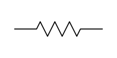
R
Limits current and drops voltage. On the bench: measure resistance in-circuit only with power off, and expect parallel paths to read low — lift one leg to be sure. Open resistors usually show a burn mark or read OL.Tools and component knowledge are ammunition; methodology is marksmanship. This module is the universal process that makes you efficient (fewest measurements to the answer) and accurate (the answer is actually the root cause). Memorize the sequence; the rest of your career is refining it.
The sequence
1. Understand the complaint → 2. Look → 3. Power-off checks → 4. Power-on: rails → 5. Heartbeat (clock & reset) → 6. Localize (half-split) → 7. Confirm the component → 8. Root-cause → 9. Repair, verify, document
1. Understand the complaint
Read the work order / ATE failure ticket / squawk completely before touching the board. What test failed, with what measured value, against what limit? Intermittent or hard? Any history (repeat offender)? The failure ticket tells you where to look — it does not always tell you what is broken (a "failed resistor" at ICT may be a cracked solder joint, a bent test pin, or a neighbor loading the net — see 09 — Teradyne Machines & Automated Test (ATE)). Define "known good": get the schematic, the test spec (expected voltages/currents/waveforms), and ideally a golden board for comparison.
2. Look (and smell)
Five disciplined minutes under magnification beats an hour of probing. Aerospace shops will give you a stereo microscope — use it. Hunt for:
- Burnt/discolored parts or board areas; the smell of burnt epoxy
- Bulged/vented electrolytics; cracked MLCCs/tantalums
- Cracked, dull, or ring-fractured solder joints; lifted leads; tombstones
- Bent/recessed/corroded connector pins; broken connector tails
- Corrosion, dendrites, flux residue, liquid ingress staining
- Foreign object debris (FOD) — a loose screw or solder ball does real damage
- Missing, wrong, or backwards components (compare to the assembly drawing; remember DNP parts are supposed to be absent)
- Conformal coating damage — often marks the spot of mechanical insult
- Prior rework — a repeat-failure board's history is written in its touched-up joints
3. Power-off checks
- Fuses: continuity (never by eye).
- Each power rail to ground: ohms/diode-mode signature. Note values; compare to golden board. Dead short found here saves you from powering into it.
- Input protection parts (TVS, reverse diode) not shorted.
- Connector pins to their first destination: continuity.
4. Power-on: rails first
- Current-limited bench supply whenever the setup allows: set expected voltage, limit current just above expected draw. The current readout is your first diagnostic — too high (short/latch-up) or too low (something not starting) each prune half the fault tree.
- Measure every rail at its test point, in dependency order (28V in → 5V → 3.3V → 1.2V...). Each must be present, in tolerance, and (scope) clean. A missing rail: check its regulator's input first — don't condemn a regulator that's never been fed. A sagging rail: regulator weak, or load heavy? Lift the load (link/bead) to decide.
- A huge fraction of all dead boards die right here, in the power chain. Master modules 08 — Analog Board Troubleshooting §power supplies.
5. Heartbeat: clock and reset
For anything with a processor/FPGA: rails good → clock running (scope) → reset releasing properly (scope, single-shot on power-up). No clock or perpetual reset explains almost any "board is totally dead but rails are fine" complaint. See 07 — Digital Board Troubleshooting.
6. Localize: half-split / signal tracing
The efficiency engine. The board is a signal chain: stimulus in one end, response out the other.
- Half-split: measure at the chain's midpoint. Good there? Fault is downstream. Bad? Upstream. Each measurement halves the territory — a 16-stage chain falls in 4 measurements. Use natural midpoints: connectors, buffers, test points, stage boundaries.
- Signal tracing: inject/apply a known stimulus at the input, follow it stage by stage with the scope until it disappears or corrupts. The fault lives between the last good node and the first bad one.
- Signal injection (reverse): drive a known signal into successive points walking backward from the output until the output responds.
- Comparison: any measurement you can't interpret, make on the golden board. Diode-signature comparison (04 — DMM Mastery §5) localizes digital damage astonishingly fast.
7. Confirm the component
Before condemning a part: isolate it (lift a leg / remove it) and verify it actually fails out of circuit, or prove it with an in-circuit measurement that has no alternative explanation. The joint, the via, and the trace are suspects of equal rank with the component — "R47 open" at the tester is just as often "R47's pad cracked."
8. Root-cause
Ask why it failed before closing:
- Burnt resistor → what overloaded it? (Find the short before installing the new one.)
- Shorted TVS → what transient? (It did its job.)
- Cracked joints/via → thermal or mechanical stress; will the replacement crack too?
- Repeat-failure unit → the previous repair treated a symptom. For intermittents, use an approved reproduction method within the assembly's electrical, thermal and mechanical limits, with synchronized symptom capture. Do not improvise hot-air heating, freeze spray, board torsion or tapping on operational hardware. A correlation localizes a region, not necessarily a failed device. If the fault cannot be reproduced safely, document the exact conditions, evidence and limitations and obtain the authorized disposition; do not treat more aggressive provocation as a release requirement.
9. Repair, verify, document
- Repair per IPC-7711/7721 and shop procedure (10 — Aerospace Standards, ESD, and Workmanship) — correct part (BOM revision!), correct orientation, coating restored.
- Verify: re-run the failing test AND the full acceptance test (your repair must not have broken something else).
- Document: symptom → cause → action → verification, with measured values. In aerospace this is the product.
Failure statistics — where to bet first
Use the assembly's verified defect history to rank hypotheses. These are inspection categories, not a universal statistical ranking:
- Solder joints and interconnects — joints, vias and traces; check for a connection defect that fits the actual symptom.
- Connectors and contacts — fretting, corrosion, bent pins, cable strain
- Capacitors — electrolytics dry out, tantalums short, MLCCs crack
- Mechanical/electromechanical — relays, switches, fans
- Semiconductors — investigate operating conditions as well as the device; do not assume every failure was caused externally.
Choose the safest reversible measurement that separates the leading hypotheses. A continuity beep does not establish a connection's performance under load; a visually normal part can still be faulty.
Efficiency habits
- Predict before you probe. Write the expected value, then measure. A measurement without a prediction teaches nothing.
- Change one thing at a time, re-test after each change.
- Don't trust your memory of a measurement — log values as you go.
- Beware the second fault. Lightning/overvoltage events and cascading failures produce multiple casualties; fixing one and re-testing is how you find the next.
- Beware your own probe. A slipped tip bridges pins; a probe's capacitance can stop a marginal oscillator. If behavior changes when you touch it, that's data — and possibly your fault.
- Time-box rabbit holes. Twenty minutes without progress → step back to the sequence: what do I know, what's the cheapest measurement that splits the remaining possibilities?
Self-check
- Recite the 9-step sequence from memory.
- Board draws 10× expected current at power-up. Which steps does this prune? Short on a rail — go to power-off rail signatures / short-localization; skip signal-chain work
- ATE says C31 failed, measuring 2nF vs 100nF expected. Give three explanations beside "bad cap." Cracked solder joint/open trace to it; fixture pin not contacting; wrong/missing part installed
- What's the fastest way to halve a 12-stage signal chain fault? Measure at stage 6 — half-split
- Why must a burnt resistor never be just replaced and shipped? It's usually the victim — find the overload's cause first
Next: 07 — Digital Board Troubleshooting
Worked example & practice
Example: 28 V before a fuse and 0 V after it bracket an input-path problem. A de-energized open fuse confirms the interruption but does not establish why it opened.
Your turn: Complete the fuse and two-fault drills. Log a rejected hypothesis and the observation that rejected it.
Check: Have you separated symptom, localized fault, physical cause and verification?
Open the annotated Schematic Symbols guide · Guided physical practice
Module quiz
10 questions drawn from this module. Pass is 80% — retake as often as you like; your best score is kept on this device.