Module 01
Electronics Foundations
What you’ll be able to do
Predict voltage, current and power before reaching for a meter.
Course plan & prerequisites · Scope and sources · Revision 2026-09-10
On this page
Study an annotated diagram
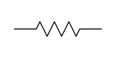
R
Limits current and drops voltage. On the bench: measure resistance in-circuit only with power off, and expect parallel paths to read low — lift one leg to be sure. Open resistors usually show a burn mark or read OL.Everything in troubleshooting reduces to predicting what voltage, current, or resistance should be at a point, measuring what it is, and explaining the difference. This module gives you the prediction tools.
1. The three quantities
| Quantity | Symbol | Unit | Plain-English meaning | What you measure it with |
|---|---|---|---|---|
| Voltage | V (or E) | volts (V) | Electrical pressure between two points | DMM in V mode, across two points |
| Current | I | amperes (A) | Flow of charge through a path | DMM in A mode, in series with the path |
| Resistance | R | ohms (Ω) | Opposition to flow | DMM in Ω mode, power off |
Key mental model: voltage is always between two points (it's a difference, like height). Current is through one point (like water flow in a pipe). Saying "the voltage at TP3" really means "voltage between TP3 and ground."
2. Ohm's Law and Power
V = I × R        I = V / R        R = V / I
P = V × I        P = I² × R       P = V² / R
- 5V across 1kΩ → I = 5/1000 = 5mA. This is the calculation you'll do most in your life.
- A part dissipating more power than rated gets hot, drifts, then dies. Discolored board = chronic overheating = look for what's drawing too much current.
Unit prefixes you must know cold: M (mega, ×1,000,000) · k (kilo, ×1,000) · m (milli, ÷1,000) · µ (micro, ÷1,000,000) · n (nano, ÷10⁹) · p (pico, ÷10¹²)
So 4.7kΩ = 4,700Ω; 100nF = 0.1µF; 2.2mA = 0.0022A.
3. Series and parallel
Series (one path, components in a chain):
- Same current through everything.
- Resistances add: R_total = R1 + R2 + …
- Voltage divides proportionally to resistance — this is the voltage divider, a common analog building block:
Vout = Vin × R2 / (R1 + R2)(R2 is the one Vout is taken across)
Parallel (components side by side between the same two nodes):
- Same voltage across everything.
- Current divides; total resistance drops below the smallest:
Two resistors:
R_total = (R1 × R2) / (R1 + R2). Two equal resistors → half.
Why this matters for repair: passive parallel paths can lower a de-energized resistance reading. A high reading is also a discrepancy, but verify part identity, probe contact, residual energy and meter behavior before naming a failed component. Authorized isolation separates the component from the surrounding network. See 04 — DMM Mastery.
4. DC vs AC
- DC — constant polarity. Power rails (3.3V, 5V, ±15V, 28V in aerospace) are DC. 28VDC is the classic aircraft bus voltage; 115VAC 400Hz is the classic aircraft AC supply (400Hz, not 60Hz — transformers can be smaller).
- AC — polarity alternates. Described by frequency (Hz) and amplitude. Amplitude has three common expressions: peak (Vp), peak-to-peak (Vpp), and RMS (the "DC-equivalent heating value"; for a sine wave, RMS = Vp ÷ √2 ≈ 0.707 × Vp).
- A DMM in V~ mode reads RMS. Cheap meters are only accurate on sine waves; a true-RMS meter measures non-sinusoidal waveforms only within its specified bandwidth, crest-factor, amplitude and coupling limits — you want true-RMS for work.
- Real signals are usually DC with AC riding on it — e.g., a 5V rail with 50mV of switching ripple. The scope's AC coupling lets you see the small AC part without the big DC offset (see 05 — Oscilloscope Mastery).
5. The passive components' jobs
- Resistor — sets current, divides voltage, pulls a line up or down, terminates a bus, senses current (tiny "shunt" values like 0.01Ω).
- Capacitor — stores charge. Blocks DC, passes AC. Its AC opposition (reactance) falls with frequency:
Xc = 1/(2πfC). Jobs: decoupling/bypass (a local energy reservoir next to every IC's power pin — those little 100nF caps everywhere), bulk filtering (big electrolytics smoothing a supply), coupling (passing signal while blocking DC), timing. - Inductor — stores energy in a magnetic field. Passes DC, opposes changing current:
Xl = 2πfL. Jobs: filters, energy storage in switching supplies, ferrite beads to choke high-frequency noise. - Time constant: an RC pair charges/discharges with τ = R×C seconds (63% per τ, ~fully in 5τ). This rules reset circuits, debouncing, and filters.
6. The semiconductors' jobs
- Diode — one-way valve. Conducts when forward-biased (anode ~0.6V above cathode for silicon), blocks reversed. Jobs: rectification, reverse-polarity protection, clamping, steering.
- Zener diode — deliberately operated in reverse breakdown at a precise voltage. Jobs: voltage reference, protection clamp.
- BJT transistor (NPN/PNP) — current-controlled switch/amplifier. Small base current controls large collector current. Quick health intuition: it's two diode junctions (B-E and B-C) back-to-back — testable with DMM diode mode.
- MOSFET (N/P-channel) — voltage-controlled switch. Gate voltage opens the drain-source channel. Dominant in power switching. A destructive failure can short drain to source; verify the actual device and circuit.
- Op-amp — a high-gain differential amplifier. With stable negative feedback and operation inside its common-mode, output swing, load and bandwidth limits, the input voltages are approximately equal. Input bias current is small, not zero. Comparators and saturated amplifiers do not obey this approximation.
- IC — anything from a 4-gate logic chip to a billion-transistor processor. To a repair tech an IC is: power pins, ground pins, inputs, outputs — verify the first two, stimulate the third, watch the fourth.
7. Grounds and returns
"Ground" is just the agreed 0V reference node. Boards often have multiple grounds (analog ground, digital ground, chassis ground) joined at one deliberate point to control noise. Two practical consequences:
- Always know which ground your black probe is on.
- A "ground" that has resistance to the real ground (cracked joint, corroded standoff) creates bizarre, intermittent symptoms — measurable as a few ohms or as voltage appearing "on ground" under load.
8. Self-check (answer without notes)
- A 330Ω resistor across 3.3V — how much current? How much power? 10mA; 33mW
- Two 10kΩ resistors in parallel? In series? 5kΩ; 20kΩ
- A voltage divider: 12V in, R1=10kΩ on top, R2=2kΩ on bottom. Vout? 2V
- Why does a 100nF cap sit next to every IC power pin? Local decoupling — supplies instantaneous current and shunts high-frequency noise to ground
- Why can a low in-circuit resistor reading be inconclusive? Passive parallel paths may lower it; verify setup and use authorized isolation before judging the resistor.
Next: 02 — Reading Schematics
Worked example & practice
Example: A 5 V source across 1 kΩ predicts 5 mA and 25 mW. With two 1 kΩ resistors in series, total current is 2.5 mA and the midpoint is 2.5 V unloaded.
Your turn: Draw the current path and calculate the midpoint if the lower resistor changes to 2 kΩ. Explain why connecting a load changes it.
Check: Can you state the units and assumptions for every calculated result?
Open the annotated Schematic Symbols guide · Guided physical practice
Module quiz
10 questions drawn from this module. Pass is 80% — retake as often as you like; your best score is kept on this device.